![]()
(7/31/03) - Many, if not all, of us VW owners have run into this problem of failing brake light switches at one point or another. Seems like the original German switches last almost forever, but they aren't being made anymore. So when you need to change them out, for whatever reason, you end up with an inferior switches that just don't last. About 3 years ago I put a set of Brazilian switches in with a new master cylinder - it seemed like a good idea at the time, but they only lasted for 2 months! I later purchased a set of the last new German switches available... They worked perfect for 2 years, then one day they died also! So I stuck a couple new ones in (not German) and they failed within 3 weeks! With a little research and poking and prodding, I was able to find away that seems to fix the problem for good. A big thanks goes out to David Dubois for pioneering the original "fix" on his MG).
![]()
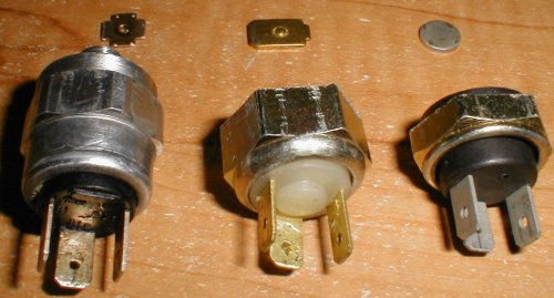
TYPES OF SWITCHES: In the picture below of cutaway switches, the one on the LEFT is a German unit. The switch in the middle is a Brazilian unit, and the switch on the right I *believe* to be a Mexican unit, but it may be another version of a Brazilian switch. I will refer to the switch in the middle as the "white plastic" version, and the switch on the right as the "black plastic" version (as they have different color insulation inserts as seen in the pic below.)
You can see that the German switch and the white plastic switch both utilize copper contacts (good), while the black plastic version utilizes stainless contacts (not so good).
![]()
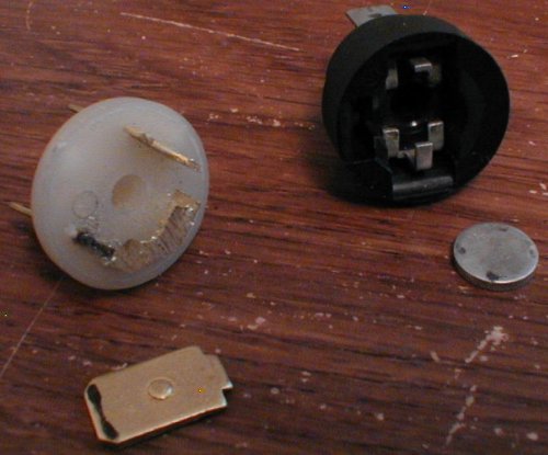
HOW THEY WORK: The insides of each of these three switches are a little different, but functionally they are the same. The picture below shows the black plastic version (with the exception of the piston/filler being from a white plastic version).
Brake fluid flows into the switch when the system is under pressure (when you are braking), and this pushes a rubber diaphragm into contact with a little plastic piston, which in turn depresses the circular metal 'wafer' which completes the circuit (the brake lights come on).
From left to right: Master cylinder end of switch, rubber diaphragm, piston, plastic filler inside switch (piston goes into the center of this), end cap which contains the spring, 'wafer', and contacts.

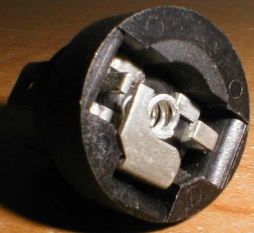
Here is a closer view of the end cap. The spring holds the 'wafer' away from the contacts until pressure is applied.
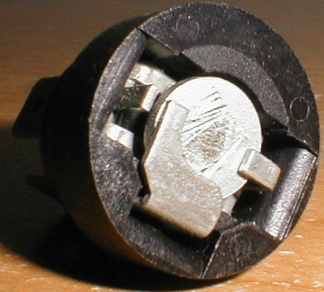
Here it is with the 'wafer' installed.
![]()
WHY THEY FAIL: I have pulled apart six switches, and so far the failure has been the same in ALL of them! You can see from the pic below that contacts are arcing and oxidizing. These switches just aren't designed to handle the load (especially in my case with SIX brakelights!)... You can see the white plastic version has a little bigger contact patch, while the black plastic version has a tiny contact patch; but in this case neither is good enough. A lubricated switch with larger contacts would probably fix the problem for good, but this is not a readily available solution (yet).
![]()
OPTIONS: One fix would be to skip the hydraulic pressure switch all-together and modify a mechanical unit to work. Perhaps a microswitch setup at the pedal, or pushrod. I would've done this myself if I had the time. The other option is to keep the hydraulic switches, but figure out a way to make them last... A simple automotive relay added to the system should fix the problem! And as added protection you can also include a capacitor and diode to the mix to aid in arc suppression (as seen in David Dubois' article here: Brake light switch relay).
While I would like to lay out the exact details in wiring everything up, the differences between my car and others is just too large. So I'm going to leave some of the details up to you. This article explains most of the procedure, but you may need to look in your manual(s) to determine which wires go to what before you can wire all this stuff up.
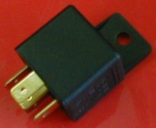
So go grab a standard automotive relay (I used a 30A Bosch I had laying around), and hook it up as follows:
30 - 12v switched (from fusebox)
87 - To brake lights
86 - 12v OUT from brake light switch
85 - Ground
(a schematic by David Dubois can be found HERE)
Since you will be using a relay, you no longer need TWO working switches. Just purchase 1 replacement, and wire the vehicle up so that the single switch operates the relay, which operates all your brakelights.
![]()
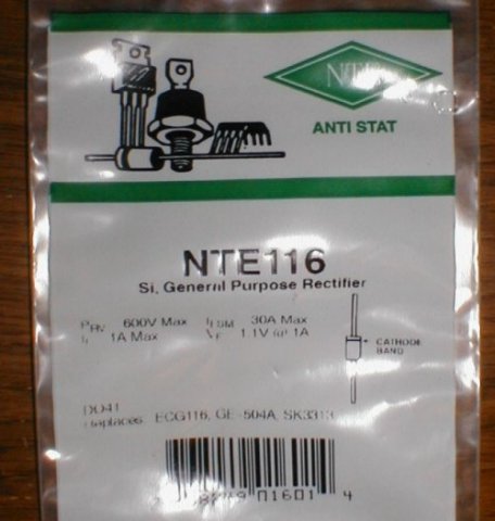
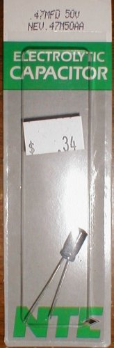
For added protection you need to buy a diode and a capacitor. The diode is a standard 1A diode (an NTE116, or 1N4005 are common). And for the capacitor you will want something around .47 micro farads.
![]()
If you decide to install the capacitor and diode, you can follow David Dubois' schematic located HERE).
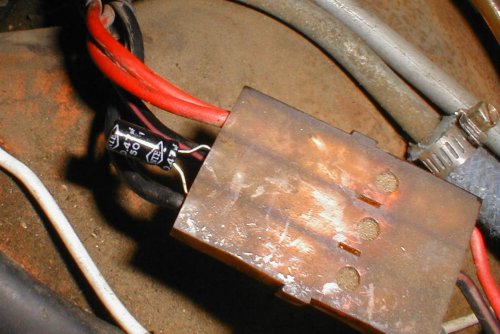
To install the diode: wire the diode across terminals 85 and 86 on the relay (with the cathode band towards terminal 86).
To install the capacitor: wire the cap across the leads of the brake light switch. I did this inside the trunk, then covered the cap and leads with RTV.
![]()
That's it! Your brake light switches should last a LOT longer now.
![]()
WARNING, use article at own risk! Please, DO NOT blame me for anything wrong in this article. I am not responsible for any damage to your vehicle, nor am I responsible for any bodily harm incurred as a result of using this article. Use this article as reference only, ALWAYS try to be as safe as possible when working on your vehicle! Respect your car, and it will respect you!